
Why I Built My First Soldering Kit (And Why You Should Too)
I decided to learn soldering after seeing a tiny LED project online. A beginner kit felt friendly and affordable.
I gathered a soldering iron, solder, wire cutters, and safety glasses. I practiced simple joints and learned to ID resistors, LEDs, and batteries.
These five projects are small and clear. They teach soldering basics, component function, and simple circuit behavior without overwhelming you. You’ll end confident with a few cool gadgets.

Project 1 — LED Keychain: Learn Soldering with a Tiny Circuit
What you’ll build
I solder a single LED, a current-limiting resistor, and a CR2032 coin-cell holder into a pocket-sized keychain light. I picked a 3mm LED for a compact beam (5mm is brighter but bulkier).
Parts & time
Step-by-step highlights
Identify polarity: longer LED lead = anode (+); flat LED rim = cathode (?). Trim leads after soldering, leaving a small fillet. Heat the pad and component lead together, feed solder to the joint (not the iron tip) until it wets both surfaces.
Tips & troubleshooting
If it won’t light, check polarity, cold joints (dull, grainy solder), or bridged pads. Test with a multimeter or temporarily touch LED to a fresh battery to confirm orientation. Work in a ventilated spot and clip leads safely to avoid shorts. Skills learned: steady hand placement, correct heating, and recognizing good vs. cold joints.
Project 2 — Blinking LED with a Timer Chip: Make Your Light Come Alive
What I built
I made an astable multivibrator with an NE555 timer IC to blink an LED. It’s the perfect step up from a single-LED project: you learn to read a simple schematic, place an IC on a small protoboard or PCB, and see how component values change behavior.
How I wired it
I followed a standard 555 astable schematic: two resistors and a capacitor set the on/off timing, output drives an LED (with a resistor). Quick tips:
Soldering tips & pitfalls
Solder one corner of the socket first, check alignment, then solder remaining pins. Use flux to avoid bridged pins and wick if you make a bridge. Avoid overheating the IC by soldering the socket instead of the chip itself.
Project 3 — Tiny Buzzer Alarm: Add Sound to Your Builds
What I built
I assembled a compact buzzer circuit using a small piezo element, a transistor driver, a switch input, and a few resistors. It’s a great step after LEDs — you hear your soldering work!
Parts & polarity
I used a passive piezo disc (cheap Murata-style) and a 2N2222 transistor. Note: passive piezos have no polarity; active buzzer modules do. If you buy modules, you’ll often see a marked + terminal and an onboard oscillator.
Assembly & mounting
Solder the transistor, base resistor, and switch to a tiny perf board; use short leads and a bit of flux. Mount the piezo to a plastic housing with hot glue so sound isn’t muffled — leave a small air cavity for better tone.
Quick variation
Add a 555 timer or microcontroller to pulse the buzzer for beeps, or tie it to a sensor as a simple alert.
Debugging tips
Next, I take those sensing ideas further with a light?sensing night light.
Project 4 — Light-Sensing Night Light: Learn Sensors and Transistors
What I built
I made an LED lamp that turns on when the room gets dark using an LDR (photoresistor) and an NPN transistor as a switch. It’s the first time I mixed passive sensing with an active semiconductor; watching the LED respond to real light feels rewarding.
Parts & polarity
Typical parts: GL5516 or generic LDR, 2N3904 (or 2N2222/BC547) transistor, a 10k fixed resistor or 10k pot, one LED + appropriate series resistor (?220? at 5V), and a 3–9V supply. LDRs aren’t polarized; transistor pins matter.

Assembly & wiring
Build a voltage divider: LDR + fixed resistor to form a node that feeds the transistor base through a 4.7k base resistor. Emitter to ground, collector to LED+resistor to Vcc. Read the schematic carefully — base current is limited by that resistor.
Testing & tips
Project 5 — Multi-LED Badge: Combine Skills into a Fun Wearable
Design & layout
I sketched a 6–9 LED pattern on cardboard first, planning a shared power rail and a single ground bus to keep routing tidy. I chose frosted 5mm LEDs for a soft glow and a CR2032 holder (or a tiny LiPo) for compact power. Mapping where resistors and a slide switch sit prevents last-minute reroutes.
Soldering & wiring
I staggered LED heights, trimmed leads flush, and used a thicker enamel wire for Vcc and ground rails so solder points stayed consistent. Solder each joint quickly, apply flux, and inspect for bridges. I liked using a mini SPDT slide switch for reliable on/off.
Finishing touches
Heat-shrink tubing on exposed joints, and a dab of clear epoxy over the board, made it durable enough to wear. I once wore mine to a meetup and people asked where I bought it—proud moment.
Scale & variations
Add more LEDs, use WS2812 strips for color control, or 3D-printed diffusers to elevate the look. With the badge complete, I’m ready to wrap up and suggest next steps.
Wrapping Up and Next Steps
I learned soldering basics, LEDs, timers, buzzers, sensors, and wearable assembly through these five projects.
Next try a simple theremin, USB charger, or expanded badge—practice patience, prioritize safety, and tinkering.
Loved this write-up — super encouraging! I built the LED keychain from Project 1 last weekend and it was ridiculously satisfying to see that tiny circuit light up ?
A couple of notes from my attempt:
– The magnifier on my 110W WEP Soldering Station Kit saved my eyes (and my patience).
– I accidentally bridged two pads at first — tip: use a wick and a steady hand.
Thanks for the clear photos. Already eyeing Project 5 for a wearable Xmas badge ?
Omg same — bridged two pads and panicked. Solder wick + lots of patience is the secret. Also, how long did your keychain battery last?
So glad it worked for you, Laura — great troubleshooting tips! The 110W WEP station is a beast for small parts; glad the magnifier helped. If you want cleaner joints, try tinning both the pad and the lead before joining them.
Nice! Also try using a smaller tip when working on tiny pads — makes overheating less likely. I learned that the hard way ?
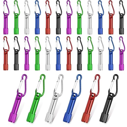
First-time solder-er here — your intro section made me bite the bullet. Picked up the 30-Pack Mini Carabiner Keychain LED Flashlights for Project 1 (they were cheap and cheerful).
Some noob notes:
– My soldering technique was shakey; practice on spare wires first.
– I don’t have steady hands, so using the magnifier helped a ton.
– The article mentioned both 110W and 60W irons — is there a strong reason to get one over the other for starter projects? I’m confused lol.
Thanks for the inspiration, though. Gonna try the night light next.
And don’t forget safety: work in a ventilated area and use a damp sponge for tip cleaning. You’ll improve quickly with a few projects under your belt.
From my experience: go for a decent tip size (small conical or chisel) — that helps more than watts for tiny work. Also practice with some spare wires like you said.
Welcome, Daniel! Either iron works — the 110W station (temp-controlled) is better for tiny electronics and consistent results; the 60W portable is fine if you need something cheaper/compact. For beginners I usually recommend a temp-controlled station if budget allows.
I appreciated the step-by-step, but I gotta say the explanation for the timer chip in Project 2 felt rushed. If you’re new to 555 timers, some schematics or a quick primer would help.
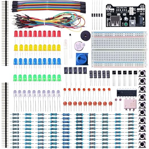
That said, the suggestion to grab an ELEGOO 235-Piece kit is spot on — tons of parts to mess around with. Still, I wanted just a bit more theory before diving in.
If it helps: build the circuit on a breadboard first with the ELEGOO kit parts, watch the LED blink, then solder. Seeing it physically helps a lot.
Good point, Marcus — thanks for the feedback. I’ll add a short explainer for the 555 timer (pin functions + common astable config) in the next update. Meanwhile, this simple resource breaks it down: think of pins 2/6 as the trigger/threshold pair and pin 3 as the output.
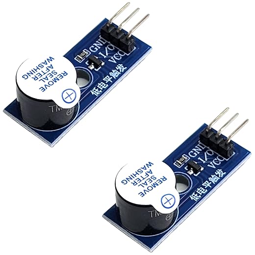
The buzzer project was my favorite — love that you included sound! Picked up the Active Piezo Buzzer Module Pack for Microcontrollers and it worked great with the tiny buzzer alarm build.
One tiny critique: maybe mention that buzzers can be loud in enclosed spaces (sleeping roommates beware ?). Also, wiring polarity matters on some modules — learned that the hard way.
For anyone worried about volume, adding a small resistor or using PWM to lower duty cycle helps. Or glue it inside a sponge ?
Great catch on polarity and volume, Tina — I’ll add a note about decoupling/enclosures and recommended resistor values if using direct drive from microcontrollers.
Also check if your buzzer is active vs passive. Active buzzers just need power; passive ones need a tone signal. Your Active Piezo pack sounds ideal though.
Also — if someone wants to integrate the buzzer with Project 4 (light-sensing night light), you can trigger the buzzer when light falls below a threshold. Fun combo!
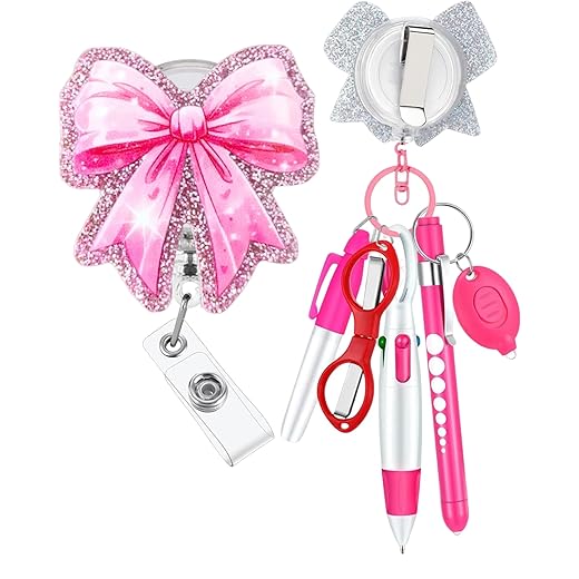
Haha loved the Multi-LED Badge — turned mine into a tiny rave accessory for a party and people actually asked where I bought it lol. Also used a 6-Piece Nurse Badge Reel and pen set to clip it on easily.
Tiny note: some of the LEDs I used were ultra-bright and I forgot current-limiting resistors for a sec. ? Oops.
Pro tip: put the resistor on the LED’s anode and tuck it under the badge to keep it neat. Also, if the nurse reel looks bulky, trim the housing carefully.
That sounds awesome, Sophie! Glad the badge saw real-world use. Definitely add resistors — LEDs love current limits ?. I’ll emphasize that in the guide.
Really liked the night light section. The explanation around the LDR and transistor pair was clear, and the hands-on part of adjusting the sensitivity made it feel like a small lab experiment.
A couple things I did differently:
1) Used the 60W Portable Soldering Iron Kit with Five Tips because my workspace is tiny and I didn’t want the heavy station. It got hot enough for the joints.
2) If you’re new to transistors, label the pins (E, B, C) before soldering — saved me from a backward install.
Minor gripe: the parts list could link the exact resistor and transistor specs. Otherwise, great article.
I swapped in a MOSFET for the transistor in a later version — lower on-resistance and it ran cooler for higher LED currents. Not necessary for the basic project but neat to try.
Thanks Owen — I’ll add explicit part numbers and suggested transistor types (e.g., 2N2222 or BC547) in the parts list. Good call on labeling pins!
Also, for readers using portable irons: make sure to work quickly to avoid cold joints. A temp-controlled station like the 110W WEP is more forgiving, but portable irons are fine with practice.
Little trick: use a piece of masking tape to mark pin orientation before you solder anything. Cheap and effective.
Agreed on labeling — saved me too. Also, if you use the smaller 60W iron, try to pre-tin the tip and the leads; makes the joins much faster.