Introduction: Why I Test Capacitors — Fast and Safe
I’ll walk you through testing capacitors safely and accurately in five clear steps, from identifying components to interpreting results, no advanced lab required, with concise troubleshooting tips for beginners today.
Requirements: What I Use and Need
I use a DMM (capacitance preferred), insulated tools, safety goggles, soldering/desoldering tools, parts tray, circuit schematic, and soldering and safety skills.
Step 1: Identify and Isolate the Capacitor
Don’t guess — find the culprit like a detective; why orientation and labeling matter.Inspect the board and schematic to locate the target capacitor; I note polarity markings and component values.
I isolate the capacitor before testing — I lift one leg or desolder it — because in?circuit measurements can be misleading. I photograph the part and record the reference designator for accurate reassembly.

Step 2: Discharge the Capacitor Safely
Never skip this — a shocking mistake is painfully common. Want to avoid it?Discharge the capacitor with a high-value resistor (10k–100k?) across the leads, holding the resistor with insulated probes or a resistor holder. Avoid shorting with screwdrivers — I once blew a PCB trace that way. After waiting several seconds, verify the voltage is near zero with my multimeter. Ground myself and keep nearby components protected from accidental currents.

Step 3: Measure Capacitance and ESR
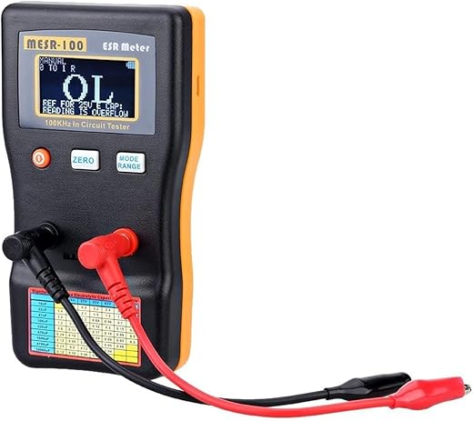
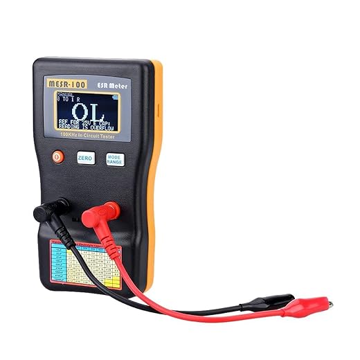
Want accurate results? Don’t rely on voltage alone — these quick checks reveal the truth.Use a capacitance meter or my multimeter’s capacitance mode (I use a handheld LCR) to measure the value; disconnect the part when necessary for accuracy. Measure ESR with a dedicated ESR meter; high ESR often signals failure even if capacitance reads close. For example, a labeled 10µF ±20% should read ~8–12µF; ESR >1? on small electrolytics usually means replace.

Step 4: Interpret Results and Decide
Is 10% off OK? Here’s how I decide whether to repair or replace — no guesswork.Compare measured capacitance against the labeled value and tolerance; I accept small deviations within tolerance. Replace capacitors showing elevated ESR, significant leakage, or physical damage. For power supplies or audio paths I’m conservative and replace marginal parts.
I note my decision and rationale in my log.
Step 5: Reinstall and Test in Circuit
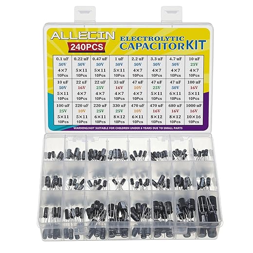
Reassemble like a pro — testing under real conditions reveals hidden problems.Reinstall the replacement capacitor, observing polarity and using proper soldering technique with minimal heat.
I clean flux residue and secure leads; for example, trim leads flush and add hot glue on tall parts.
Power up from a current-limited supply and monitor:
I run functional tests (e.g., audio, boot, charge). If anomalies appear I power down, re-check connections or component choice, then label the replacement.

Conclusion: Confident, Safe Capacitor Testing
I now follow these five steps—identify, discharge, measure, decide, reinstall—to stay safe, speed repairs, prevent repeat failures; try this process and share your results to improve and inspire others today.
Solid post. Kept it short, tried it, replaced 3 bad caps in an old amp. Peace restored to my speakers ?
Fantastic — glad the guide helped bring the amp back to life!
Haha, music saved. Nice win.
Loved Step 3. Measuring capacitance and ESR is honestly the fun part for me.
One tip: for SMD caps I use tweezers and a little kapton tape to lift them out if possible — makes bench testing easier.
Also, some boards let you test in-circuit but be careful of parallel paths that skew readings.
Do you have a favorite tool for removing SMDs safely? I’ve melted a few pads ?
Great additions, Diego. We mentioned in-circuit caveats in Step 3, but your practical handling tips for SMD caps are super useful.
Agreed on the in-circuit caution. I’ve had readings that made a cap look shorted but it was actually another component in parallel.
Any advice for testing tiny SMD ceramic caps? They’re notorious for measuring weird because of board stray capacitance.
Do you desolder, or is there an in-circuit trick?
SMD ceramics are tough in-circuit. If possible desolder a sample and bench test. Otherwise, try comparing with a known-good board or unplugging adjacent components if feasible. Also, using a meter with a ‘capacitance in-circuit’ mode helps but isn’t foolproof.
If desoldering isn’t an option, measure under different board power states (powered off vs. standby) to see changes — sometimes that reveals the culprit.
I usually desolder at least one to get a baseline. If it’s a batch of caps, test a few to decide.
Nice guide, small addition: for really stubborn caps I sometimes use the ESR trend method — track ESR over time during load cycles to spot intermittent degradation.
Not beginner level, but handy for troubleshooting flakey power issues.
Just don’t forget isolation and discharge first!
That’s a valuable advanced tip, Marcus. ESR trend analysis can catch aging caps that still pass static tests.
Ooh, sounds interesting. Any cheap tools for trend logging or is this more lab gear?
You can rig up a small data logger with an Arduino + ADC and an external ESR probe if you’re DIY-inclined. Not super cheap but doable.
Great guide — simple and to the point.
I especially liked the safety emphasis in Step 2. Too many people forget to discharge first and end up with a nasty surprise.
One thing I do differently: I label caps I remove so I don’t mix them up during reinstall.
Also, a quick note on electrolytics — check for bulging or leakage before even touching them.
Thanks for the clear steps!
Bulging caps are the worst. I always photograph the board before starting so I can reference placement later.
Thanks, Laura — glad it helped! Labeling is a great tip, especially when you’re dealing with multiple caps on a board.
Yep, labeling saved me once when I was repairing an audio amp. Took me ages to figure out why it hummed ?
Nice and easy — felt like a recipe for electronics cooks ?
Only gripe is that some meters lie about ESR. Took me a while to trust mine.
True! Cheap meters can be off. I bought a mid-range LCR meter and it’s night and day.
Good point, Ethan. We tried to note that meter accuracy varies. If you’re doing lots of testing, a dedicated ESR meter or a known-good LCR meter is worth the investment.
Good walkthrough, but I felt the article could use more photos or a short video for Step 2 (discharging). Words are fine but a visual would help beginners.
Also maybe include a short equipment list at the top (what meter/model is used). Just my two cents.
If they do add a video, hope they show how to hold the resistor leads safely and use insulated clips.
Agreed. A quick vid showing safe discharge techniques would have saved me some guesswork when I started.
Thanks, Priya. That’s valid feedback — we’ll work on adding a short demo video and an equipment list in an update.
Yes please! Even a simple photo of the resistor discharge method would be enough for me.
Quick question: what ESR value would you consider ‘bad’ for a 100 µF electrolytic used in a power supply? I’m trying to decide whether to replace some old caps.
Thanks!
If you post the meter readings and the cap markings someone can help interpret them ?
It depends on the original spec, but a rough rule: if ESR has increased by 3-4x from the expected value or from a known-good cap of the same type, consider replacing. For power supply caps, low ESR is important — if you’re seeing >1? where you expect 0.1–0.3?, that’s a red flag.
Also check capacitance — sometimes ESR is okay but cap loses capacitance. Both matter.
I learned this the hard way: once I thought a cap was dead but it was just charged and my meter read weird values.?
Now I always discharge, test, then let it sit and test again. Two readings saved me a replacement once.
Also, tiny typo on step numbering (Step 1 is labeled twice?), maybe fix that — no biggie but caught my eye.
Yikes, glad you’re okay! Thanks for the tip about repeating the measurement and for pointing out the numbering typo — we’ll correct that.
Repeating readings is smart. Capacitors can behave oddly if they’re partially charged.