
Build a Simple Audio Amplifier — Fast and Fun
I’ll walk you through a compact, 4-step DIY audio amp I built and tested. I keep instructions clear, practical, and friendly so you can go from parts to sound quickly and confidently with minimal fuss.
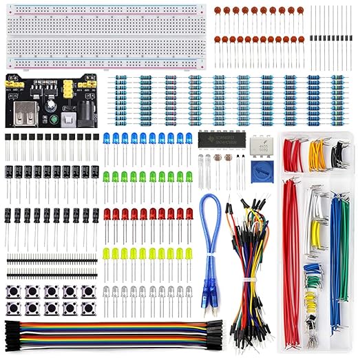
What You’ll Need
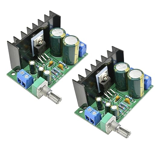
Step 1 — Choose the Right Amplifier Chip
Why I picked a tiny chip that punches way above its weight — could your choice make or break the build?Choose the amplifier chip based on power output, supply voltage, ease of wiring, and availability. Compare the LM386 (low-voltage, minimal external parts, ideal for battery portable amps; limited power/gain) with small TDA chips (higher output but more heat, heatsinks, and external components).
Pick my chip: I chose the LM386 for a 9V portable test amp for its simplicity. Source authentic parts from Mouser, Digi-Key, Adafruit or reputable sellers. Check the manufacturer datasheet for key pins: power (Vcc), input, output, and gain.

Step 2 — Layout and Wiring on Breadboard
Want sound in minutes? My neat breadboard trick keeps mistakes low and patience high.Place the chip straddling the center gap; I use an LM386 so pins align easily. Route the ground rail first, then position input components (input coupling cap, gain resistor/cap, gain cap) close to the chip. Connect bypass caps and speaker coupling near the output pin.
Move to perfboard/PCB when you want permanence, better grounding, or heat management.
Step 3 — Powering Up and Initial Tests
Don’t fry it — my quick checks caught two common rookie mistakes and saved the amp.Check for shorts, correct polarity, and that decoupling caps are fitted before applying power. I power the circuit from a current?limited bench supply or via a 10–100 ? series resistor. Listen for hum, then inject a low?level signal (phone headphone out or a 1 kHz, ?20 dBV sine) to confirm output.

Step 4 — Tuning, Enclosure, and Troubleshooting
Transform a test board into a pocket amp — small tweaks that dramatically improve sound.Adjust gain for clean volume: I lower the input pot, then raise until the first clipping, and keep a 6–10 dB safety margin. Fit 10–100 µF bypass caps to tame low-end.
Add tone shaping: Install a passive RC tone stack or small active tone control; I audition rock and vocals while tweaking.
Ensure thermal safety: Mount a heatsink, use thermal paste, and consider a thermal cutoff if it runs hot.
Mount enclosure and wire: Use rubber mounts, shielded short input leads, star ground, switched input jack and front power switch; I secure speaker with star washers.
Upgrade: consider higher?power chips or add a preamp stage I’ve used.

Ready to Hear It Play
I promise if you follow these four steps you’ll build and understand a working amp; tinker freely, share your results with me, and start improving sound—give it a try now.
Quick question — in Step 2 you show two wiring options on the breadboard. Is there a reason to prefer the second layout? I tried the first and got intermittent pops when touching the board. Maybe my breadboard is old? ugh.
Also, sorry for the typos earlier ?
Intermittent pops = bad contact or poor ground. I keep a small contact cleaner for old boards, works wonders.
The second layout aims to separate signal paths from power rails, which reduces coupling and pops. Old breadboards with oxidized contacts are often the culprit — try a different board or re-seat the components.
If you have a spare jumper, rewire the most critical connections with fresh leads. Sometimes the cheap wires are the problem, not the board.
Thanks for this — I’m a complete beginner and followed Steps 1–3 slowly. Power-up test was nerve-wracking: LED lit, no smoke, but no sound. Turned out my input jack was wired TRS instead of TS. Fixed that and it sang!
A few beginner notes:
– Check your jacks and switches for the right wiring type.
– Use a low-volume test with headphones before hooking up big speakers.
– Keep a multimeter handy to verify voltages at the chip pins.
Really enjoyed the guide, felt encouraging not condescending.
Excellent troubleshooting steps, Jasmine — those small wiring differences trip up a lot of beginners. I’ll add a short section on jack types and wiring diagrams.
Good call on the multimeter — it helps catch so many silly mistakes early on.
Same here when I started — saved my speakers by testing with headphones first. Also check polarity on speaker wires, happens more than you’d think.
For headphone testing, use cheap closed-back headphones to avoid bleeding into the room 🙂
Long post with a few lessons learned:
1) I misread the pinout for the chip — doh. Double-check pin labels before soldering!
2) On a breadboard, grounding is everything. I had hum until I tied all the grounds properly and used a star ground for the sensitive input.
3) The tuning section helped me dial out a bit of high-frequency hiss by adjusting the feedback cap values.
4) Enclosure: drilled holes too close to the faceplate and cracked the plexi. ? Measure twice, drill once.
Overall, great guide, but maybe add a small checklist for pinouts and grounding for beginners.
If anyone wants, I can post a quick diagram of the grounding star and recommended cap placements in a follow-up comment.
Oof on the plexi — been there. For enclosures, clamps + masking tape = lifesaver when drilling.
Great detailed feedback, Nora — thanks! I’ll add a quick pinout checklist and a grounding diagram to the guide. The star ground tip is especially useful for beginners.
Star grounding solved my hum too. Also try adding a small resistor (like 10?) in series with the input to tame RF pickup if you live near busy electronics.
Awesome walkthrough — I built the amp over the weekend and it actually works! Followed Step 1 and picked a pretty forgiving chip, then used the breadboard layout from Step 2.
Couple of tips from my side: keep the input and output wires short, and route the power rails away from the signal path. I also added a small coupling cap on the output while testing to protect my speakers.
Sound is clean up to moderate volumes, but starts to distort if I push it hard (probably my PSU). Highly recommend this for a first DIY amp.
Nice! Which chip did you use? I’m deciding between two similar ones and would love to hear which was more forgiving.
Thanks for the report, Liam — glad it worked! If you see distortion at higher volumes, try a stiffer power supply and add decoupling caps close to the amp chip as in Step 3. That usually helps.
Short wires + big caps = happy amp. Also watch the breadboard contact quality — they can be flaky if you move the board around.
Nice intro guide, but a couple of constructive points:
– The guide glosses over thermal design; even modest amps can heat up under load. A note about thermal runaway and mounting is warranted.
– No PCB option or suggested footprint is shown. Breadboards are great for learning, but a simple PCB layout would help those wanting a permanent build.
– Could use a short troubleshooting flowchart for common faults (no power, hum, one channel only).
Still, very approachable for newbies. Would love an advanced follow-up.
Thanks Marcus — fair points. I’m planning an advanced follow-up that covers PCB footprints, thermal considerations, and a troubleshooting flowchart. I’ll try to have schematics and a small PCB layout in that post.
Agree on the PCB — once you move off the breadboard, the build becomes way more reliable. Even a perfboard layout would be a nice intermediate step.
Loved the humor in the guide — “Ready to Hear It Play” felt like a tiny victory lap ?
I did run into a weird quirk: amp powered up fine but only one channel worked until I reseated the chip. Breadboards, man… never trust them completely.
Good point about testing channels — swapping outputs is a fast diagnostic to isolate whether it’s the chip, wiring, or the speaker.
Reseating helps a lot. Also try swapping channels with the speaker to see if it’s the board or the speaker.
I appreciate the enclosure and tuning section a lot. A few practical additions that helped me a ton:
– Use rubber grommets where wires pass through metal enclosures to avoid shorts.
– Mount the amplifier chip on a small heatsink even if the guide says it might be optional — temps add up after long play.
– For tone tuning, small changes in the feedback cap (10nF ? 22nF) noticeably change bass response; go slow and listen between changes.
Also, for anyone making a portable build, consider adding an inline fuse on the power rail. Safety first!
If anyone posts build photos, I’ll create a ‘community builds’ section in the article to showcase them — submit links here if you want.
Would love to see photos of your enclosure job, Maya — grommets and neat cable routing make a big difference.
On the heatsink note: you don’t need a giant one for low-power amps, but even a small tab reduces thermal throttling. Plus it looks pro ?
Totally agree on tuning slowly. I learned the hard way by swapping caps randomly and then wondering why my amp sounded muddy.
Excellent practical tips, Maya — I’ll update the enclosure section to mention grommets and a recommended heatsink size. Inline fuses are a great safety reminder too.