Decode Faster: Meet Your Logic Analyzer
I guide you through a compact 4-step process to set up a logic analyzer, capture signals, decode protocols, and interpret results. I make it quick, even with little time left.
Requirements
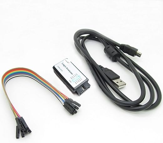
I use:
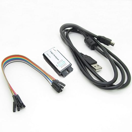
Step 1: Prepare and Connect
Want faster captures? I always double-check grounds — that tiny habit saves hours and prevents phantom glitches.Power down the target and check supply rails with a multimeter.
Attach ground before probes; clip signals to relevant pins and assign channels logically (e.g., SCLK?CH0).
Set sampling rate ?10× the highest frequency (e.g., 1 MHz ? 10 MHz) and configure input thresholds.
Document pinouts and label connectors so I can reproduce captures; check probe bandwidth and keep ground leads short.

Step 2: Capture Clean Signals
Think every trace matters? I treat noise like a liar — with the right filters it can't hide the truth.Power the system and run a quick baseline capture. I set a targeted trigger — level, edge, or protocol match — to avoid drowning in data (e.g., trigger on CS falling edge for SPI).
I adjust buffer depth and sample mode to capture the full transaction and enable pre-trigger capture so I see what led up to the event.
I use hardware filtering or reduce bandwidth when noise dominates. I repeat captures while changing conditions until I get consistent, representative traces for decoding and saving time.

Step 3: Decode Protocols Intuitively
Why stare at pulses? I translate waveforms into meaningful packets — often faster than reading a datasheet.Load captures into my logic analyzer software and enable built-in decoders (I2C, SPI, UART, CAN). Align clock and data channels, set bit order and sampling point, and enter baud/clock rates from datasheets — e.g., I2C 100 kHz, SPI CPOL=0 CPHA=1, UART 115200, sampling mid-bit.
When built-in decoders fail, write a simple Python or plugin script to parse timings and frames. Inspect framing errors, unexpected ACKs, and CRC mismatches; cross-check decoded packets with device documentation until they match. Save golden captures and annotate suspicious transactions for quick review.
Step 4: Interpret and Iterate
Want root causes, not guesses? I turn decoded packets into hypotheses and prove them with targeted tests.Review decoded transactions and timeline charts to identify anomalies, timing violations, or unexpected sequences.
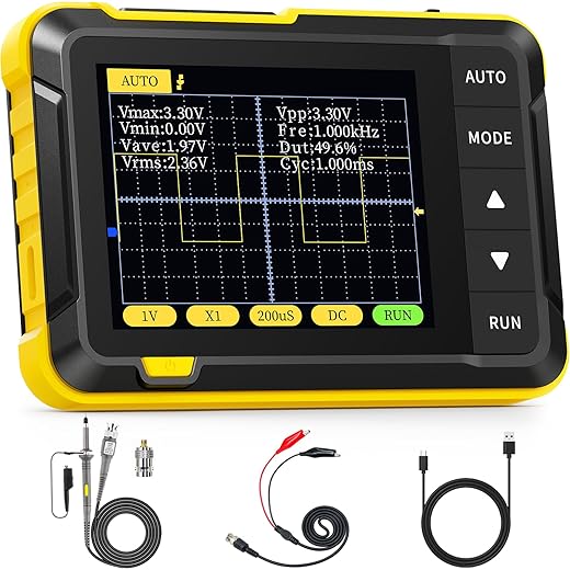
I correlate logic captures with firmware logs and oscilloscope measurements — match timestamps and trigger events to pinpoint root causes.
Conclusion: Decode Faster Today
I summarized a focused 4-step workflow; I set up, capture, decode, and iterate to turn noisy signals into clear insights. Try it, share your results, and speed your debugging today.
Love the step-by-step flow — super practical!
A couple things I learned the hard way when I first tried this:
1) Always connect the ground clip BEFORE the probe tip (saved me from mystery floating signals).
2) Use short ground leads — loop area kills your signal clarity.
Also, the Decode Protocols section made adding I2C and UART decoders feel way less scary. ?
Question: the guide mentions ‘prepare and connect’ — any tips for probing 3.3V vs 5V devices safely?
Also watch out for mixed-voltage buses — I once fried a sensor by assuming everything was 3.3V lol. ?
Short ground leads = golden rule. +1
If your analyzer supports a dedicated ground spring/clip, use that. For 5V lines, a simple logic-level converter will do the trick.
Great points, Emily — thanks for sharing! For 3.3V vs 5V, many analyzers have selectable input levels or tolerant inputs, but when in doubt use a level shifter or a voltage divider on the signal (not on ground). Also consider using the analyzer’s ground reference or an isolated probe if the target isn’t referenced to your bench ground.
Nice write-up. I liked the Capture Clean Signals section — but I still get aliasing sometimes.
What sampling rate do you guys recommend relative to clock frequency? The guide says ‘sample faster’ but curious if there’s a rule of thumb (like 10x?).
Also, any pre-filtering tips before capture? My bench has a bit of RF noise.
Good question. As a rule of thumb for digital signals, aim for at least 4–10 samples per bit edge when you want reliable decoding. For timing analysis or capturing short pulses use higher rates. For RF/noisy benches, short probes/ground, shielding, and add small RC low-pass filtering only if it won’t distort the protocol timing. Differential probes or proper grounding often help more than filtering.
I usually set samplerate to 8x expected bit-rate for UART/I2C and up to 20x for high-speed SPI. Works well for me.
Also consider using the analyzer’s digital decimation or pre-trigger buffer features so you don’t miss short glitches.
If you have aliasing, try moving the probe ground to a different point — sometimes ground loops are the culprit, not the analyzer’s sample rate.
Quick question — the guide mentions ‘decoders’ and a list of protocols. Is there an easy way to add custom decoders (like for a quirky proprietary protocol)?
Many analyzers offer scripting or plugin APIs (Python/Lua) for custom decoders. Check your tool’s docs — often you can parse the raw digital stream and implement the state machine for your protocol. If not built-in, some communities share custom decoders you can import.
Yep — I wrote a tiny Python decoder once. Not hard if your protocol has clear framing/preamble. Worst case: export raw samples and post-process offline.
I read the ‘Decode Protocols Intuitively’ bit and laughed — “intuitively” until your device uses open-drain lines and inverted logic ?
Real talk: does the decoder handle inverted TTL/CMOS levels automatically or do you have to flip bits in software? Sometimes I end up manually inverting and it feels clunky.
Most analyzers let you invert inputs per channel or set the input threshold mode. If your tool doesn’t, some allow you to apply a simple invert in the decode settings. For open-drain, enable pull-ups on the bus or configure the analyzer inputs to tolerate the idle high state.
If your analyzer is old-school, you might need to add a tiny pull-up resistor and tell the software about the bus idle state. Modern ones usually handle it, but always check the channel settings first.
Useful guide. One concern: battery-powered devices and ground references. When your device is floating or powered by battery, is it okay to clip ground to the analyzer? I worry about creating ground loops or injecting noise.
Also, have any of you tried differential probes with a logic analyzer? Worth it or overkill for most hobby projects?
If the device is battery-powered and truly floating, connecting the analyzer ground is usually safe but be mindful of any other connections (like USB, power supplies) that can create loops. For sensitive or isolated systems, use isolated or battery-powered analyzers or differential probes. Differential probes are great for noisy or high-common-mode environments, but for most low-speed hobby projects they’re often overkill.
Differential probes = game changer for power rails and mixed-signal boards, but expensive. For simple digital buses, cheaper single-ended probes + good grounding work fine.
If you’re unsure, try a quick continuity test to see if grounds are already tied somewhere. That can prevent accidental loops.
This guide is solid — especially Step 4 about iterating. A few practical habits that helped me:
– Save presets per project (sampling rate, channels, decoders) so you don’t repeat setup.
– Take screenshots with annotations when you find a weird pattern. Future-you will thank present-you.
– Common mistake: probs — I mean probing — with long wires and then blaming the code. ?
Also: anyone else keep a cheat-sheet of protocol timings? I paste that next to my monitor.
I also export the capture files (CSV/waveforms) for long-term archiving. Sometimes bugs resurface months later and old captures explain things.
Love the presets tip — absolutely crucial for efficiency. Screenshots + annotations make collaboration so much easier. And LOL at ‘probs’ ?
Probing mistakes FTW. I once used a breadboard for high-speed SPI and blamed the MCU for ages. Lesson learned: solid connections matter.
Saved presets are a lifesaver when switching between 3.3V battery projects and 5V mains-powered stuff.
Cheat-sheet here too. I keep PCB trace/ref schematics beside me — helps when the analyzer shows stray toggles and you need to find the culprit.